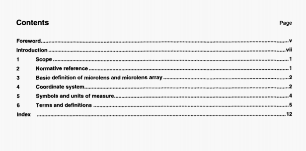
ISO 14880-1 pdf download – Optics and photonics Microlens arrays -Part 1: Vocabulary.
6.1.2
front focal length
distance from the vertex of the microlens to the poe1- hon of the focus given by finding the maximum of the power density distribution when collimated radiation s incident from the back of the substrate
NOTE The front focal length is expressed in millimetres.
6.1.3
back focal length fb
distance from the back surface of the substrate to the position of the focal point, when collimated radiation is incident from the lens side of the substrate
NOTE 1 The distance is deternined by finding the maximum of the top of the power dens4ty distribution.
NOTE 2 The back focal length is expressed in millimetres.
6.1.4
radius of curvature
distance from the vertex of the microlens to the centre of curvature of the lens surface
NOTE The radius of curvature is expressed in millimetres.
6.1.5
wavefront aberration
root mean square of deviation of the wavefront from an ideal spherical or other wavefront
NOTE The waveS ront aberration is expressed in parts of the wavelength. A.
6.1.6
chromatic aberration
change of the focal length with wavelength
NOTE 1 Chromatic aberration is characterized by the ettective Abbe-number, which is given by:
6.1.7.1
aperture shape
shape which is specified as square, circular, hexagonal, circular sector or other geometric shape
NOTE For non-regular shapes, the vertices of the lenslet aperture are to be defined by coordinates, Xa,e, Ya, where i is the lenslet number index and k is the vertex nurnber index.
6.1.7.2
geometric aperture
A9
area in which the optical radiation passing through it is deviated towards the focused image and contributes to it
NOTE 1 For graded index microlenses where no obvious boundary exists, the edge is the focus of points at wtich the change of index is 10% of the maximum value
NOTE 2 The geometric aperture is expressed in square mill4metres.
6.1.7.3
lens width 2ai, 2a2
widths of the microlens on the substrate consisting of the geometric aperture of the microlens given by a variety of shapes such as circular, semi-rectangular, elliptical and so on
NOTE I The widths are determined by measuring the longest distance (2a1) and the shortest distance (2a2) between the lens edges as shown in Figure 4. lIthe lens is circular symmetric, then the term diameter can be used.
NOTE 2 Lens widths are expressed in millimetres.
6.1.7.4
diffraction-limited optical aperture
area within which the peak-to-valley wavefront aberrations are less than one quarter of the wavelength of the radiation with which it is tested
NOTE The diffraction-limited optical aperture is expressed in square millimetres.
6.1.7.5
geometrical numerical aperture
NA9
sine of half the angle subtended by the aperture of the lens at the focal point
6.1.8
focal ratio
ratio of the focal length to the lens width of the geometrical aperture
NOTE The focal ratio is equivalent to the practical f-number.
6.1.9
imaging quality
quality of the microlens which is determined by ModuLation Transfer Function (MTF) according to (SO 15529 or the Strehi ratio
NOTE The imaging quality stiould be measured in the conjugates In which the microlenses are to be used and preferably for a range of angles of incidence.
6.1.10
focal spot size
W, Wy
half width in the x direction and y direction, respectively, at which power density is decreased to the 1/e2 irradiance levels at the practical focus point when the microlens is irradiated with a uniform plane wavefront
NOTE Focal spot sizes are expressed in micromeires.
6.2 Properties of the microlens array
6.2.1 Geometrical properties
6.2.1.1
structure of the microlens array
geometrical arrangement of the individual microlenses and feature of the substrate
NOTE There are generally two types of arrangements:
regtiar and irreguLar. Regular can be rectangular, hexagonal or polar regardiess of the overlapping of microlens on the substrate. The specification has to completely descrte the arrangement to the microlens array. The lens array positions X. Y and aperture vertex coordinates are used to define this structure. For regular structures, only the spacing and geometry are to be defined.
ISO 14880-1 pdf download – Optics and photonics Microlens arrays -Part 1: Vocabulary
