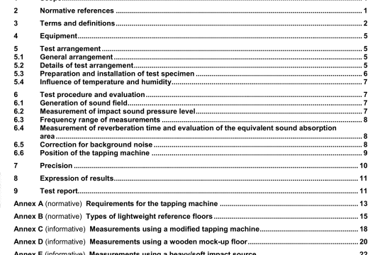
ISO 140-11 pdf download – Acoustics — Measurement of soundinsulation in buildings and of buildingelements — Part 11: Laboratory measurements of the reduction of transmitted impact sound byfloor coverings on lightweight referencefloors.
The tapping machine shall have five hammers placed in a line. The distance between the centrelines of nesghbounng hammers shall be (100 ± 3) mm.
The distance between the centre of the supports of the tapping maclime and the centrehnes of nelghbounng hammers shall be at least 100 mm. The supports shall be equipped with vibration insulating pads.
The momentum & each hammer that strikes the floor shall be that of an effective mass of 500 g that falls freely from a height of 40 mm. within tolerance limits for the momentum of 5 %. As friction of the hammer guidance has to be taken Into account, It must be ensured that not only the mass of the hammer and the falling height but also the velocity of the hammer at the impact lies within certain given limits as follows.
The mass of each hammer shall be (500± 12) g. from which it follows that the velocity at the impact must be (0.886 ± 0.022) rn/s. The tolerance limits of the velocity may be Increased to a maximum of ± 0033 m/s If it is ensured that the hammer mass lies within accordingly reduced limits of (500 ±6) g.
The falling direction of the hammers shall be perpendicular to the test surface to within ± 0.5.
The part of the hammer that slnkes the floor shall be cylindrical with a diameter of (30 ± 0,2) mm. The Impact surface shall be of hardened steel and shall be spherical with a curvature radius of (500 ± 100) mm Testing the fulfilment of this requirement may be performed lithe following ways.
a) The curvature of the impact surface is considered in compliance with the specifications if the measurement results lie within the tolerances given In Figure Al when a meter is moved over the surface on at least two lines through the centre point and being perpendicutar to each other.
The curves of Figure A.1 descnbe a curvature of 500 mm. The distance between the curves is the smallest distance that will allow both 400 mm and 600 mm radii to fall within the tolerance limits, The accuracy of the measurement shall be at least 001 mm.
b) The curvature of the hammer heads may be tested by using a sphere-meter with three feelers lying on a circle with a diameter cit 20 mm.
The tapping machine shall be self-driven. The mean time between Impacts shall be (100±5) ms. The Lime between successive impacts shall be (100±20) ms.
The time between the Impact and the lift of the hammer should be less than 80 ms.
For standard tapping machines which are used for tests of impact sound insulation of floors with soft coverings or uneven surfaces, it shall be ensured that it is possible for the hammers to fall at least 4 mm below the plane on which the supports of the tapping machine rest.
All adjustments on the standard tapping machine and verifications on the fulfilment of requirements shall be performed on a flat hard surface and the tapping machine shall be used in that condition on any test surface.
If the test surface is covered with an extremely soft covering or If the surface is very uneven so that the hammers are not able to fall down to the surface on which the supports rest, pads may be used under the supports to ensure the correct falling height of 40 mm.
When the aim of the impact sound insulation measurements on floor coverings is strong correlation between the “real impact source (e.g. a walking person) and the artifloal Impact source (eg. a tapping machine), both sources shall apply the same input force spectrum to ensure the correct ranking of the floor coverings with the rear and the artificial impact source This requires the impedance spectra of the sources to be the same. If the “real” impact source is a walking person without shoes and the artificial source Is a standard tapping machine as specified In ISO 1404, there is not strong correlation In this annex, a modification of the standard tapping machine is proposed to make its dynamic source characteristics similar to that of a walking person without shoes.
NOTE The static load of the walker is not included, which might be relevant a1h non-linear floors or floor coverings.
C.2 Modified tapping machine
C.2.1 Method A
Springs may be inserted between the hammers of the standard tapping mactime and the floor surface under test (see Figure Cl). The dynamic stiffness of each spring, s, shall be 24 kNlm ± 10%. and the loss factor q shall be 0,2 to 0,5. To maintain the same contact area compared with the excitation by an unmodified tapping machine, the springs shall have the same cross-section as the hammers. The modified tapping machine shall be adjusted to keep the same falling height of the hammers as with lhe standard tapping machne.
ISO 140-11 pdf download – Acoustics — Measurement of soundinsulation in buildings and of buildingelements — Part 11: Laboratory measurements of the reduction of transmitted impact sound byfloor coverings on lightweight referencefloors
