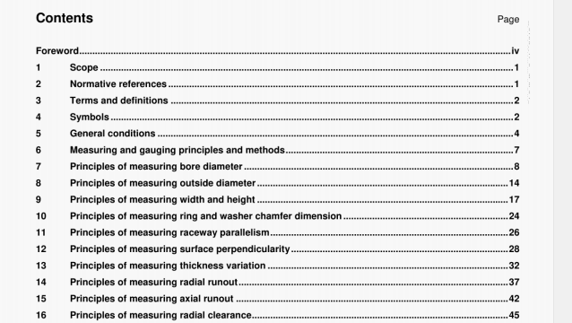
ISO 1132-2 pdf download – Rolling bearings —Tolerances—Part 2: Measuring and gauging principles and methods.
Fasten the master gauge to a surface plate.
Bearings with machined rings are measured in the free state.
For drawn cup needle roller bearings, first press the bearing into a hardened steel ring gauge of bore diameter specified in ISO 3245. The minimum radial cross-section of the ring gauge is shown in the adjacent table.
Position the bearing on the master gauge and apply the indicator in the radial direction to the approximate middle of the width on the ring outside surface.
Measure the amount of movement of the outer ring in the radial direction by applying sufficient load on the outer ring in the same radial direction as that of the indicator and in the opposite radial direction. The radial load to be applied is shown in the adjacent table.
Record indicator readings at the extreme radial positions of the outer ring. Rotate the bearing and repeat the measurement in several different angular positions to determine the largest and the smallest readings, max and ‘ws mm’
This method is applicable to radial groove ball bearings (including single-row angular contact ball bearings), 4-point-contact ball bearings and tapered roller bearings.
The radial runout of inner ring of assembled bearing, Kia, is the difference between the largest and the smallest indicator readings.
Radial runout of the inner ring of an assembled bearing is the result of several factors (e.g. variation of rolling element diameter, raceway imperfections and waviness, variation of contact angle, reference face/surface flatness and lubricant contaminant). Accurate measurement is difficult, particularly in higher precision classes of bearings. In cases of dispute, the producer and the user may agree on a more specific method, which may include the measurement of individual components as specified in 11.1, 11.2, 13.1 and 13.2.
ISO 1132-2 pdf download – Rolling bearings —Tolerances—Part 2: Measuring and gauging principles and methods
