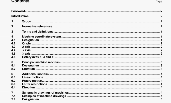
ISO 841 pdf download – Industrial automation systems and integration一Numerical control of machines一Coordinate system and motion nomenclature.
4.2 Origin
The location of the origin of the machine coordinate system shall be defined by the manufacturer.
4.3 Zaxls
4.3.1 General
The Z axis is parallel to the principal spindle of the machine, For the case where the machine has no spincae, see 4.3.4 and 4.3.5.
NOTE 1 On madlines used for milling, grinc5ng. boring, drilling and tapping, the spinc5e rotates the tod.
NOTE 2 On machines such as lathes. cylin&cal gnnders and others which generate a surface of revoluiion. the spindle rotates the work piece.
4.3.2 More than one spindle
Where there are several spindles, one shall be selected as the principal spindle, preferably perpendicular to the workholding surface.
4.3.3 Swivelling or gimballing spindle
Where the principal spindle can be swivelled or gimballed. the Z axis shal be parallel to spindle axis when the spindle is in the zero position. The preferred zero position is with the spindle perpendicular to the work-holding sLrface.
Where the princal spindle axis can be swivelled and if the extent of its motion allows it to lie in only one position parallel to one of me axes of the standard three-axis system, this standard axis is the Z axis.
Where the extent 01 the swivelling motion is such that the principal spindle can lie parallel to two of the three axes of the standard three-axis system. the Z axis is the standard axis which is perpendicular to the work holding surface of the work table of the machine, ignonng such auxiliary devices as mounting brackets or angle plates.
4.3.4 No spindle
For cutting and forming machines, the 1 axis shall be perpendicular to the work-holding surface, For coordinate measuring machines. the 1 axis should be collwiear with the acceleration of gravity vector (I.e. perpendicular to the surface of the earth).
4.3.5 DirectIon
For cutting and forming machines, the + Z axis direction is defined from the workplace to the tool holder
NOTE For tathes. the tail stodi is considered as the tool holder.
For coordinate measuring machines, the + Z direction is defined as in the opposite sense as the acceleration of
gravity vector (I.e. pointing away from the surface of the earth).
4.4 Xaxis
4.4.1 General
Where possible, the X axis shall be horizontal.
5.2.3 Moving the workpl.c.
When moving the workp.ece. the chrection of movement and the axis direction are opposite. To indicate the opposite direction, positive movements are designated with ÷ X’, + V’. -i-i’, + A’. + B’ … (i.e. the axis dwection
– X • + X’ of the workpiece movement).
6 Additional motions
6.1 LInear motions
When, in addition to the primary linear motions X. V and Z, there exists secondary linear motions parallel to the primary motions, these shall be designated LI, V and 34’ respectively. Sinidarfy, for tertiary motions, they shall be designated P. Q and I? respectively. When Imear motions exist which are not (or may not be) parallel to X, V and 1, they may be designated Li. V. W, P. Q, or Ras is most convenient.
The primary linear motions should be those nearest the pflncipal spindle, the secondary the next nearest, and the tertiary are the larthest.
For milling machines, the cutting-bit with respect to a facing slide should be designated U or P if these letters are available.
For machines with multiple units or many parallel movements, the designation of these motions may be indexed by using a letter and a number (e.g. X1, X2. …). The index shall be a positive integer greater than zero. The pnmary motion(s) may or may not have an index. Thus it is possible on one machine to have motions with and without indices.
6.2 Rotary motion
When, in addition to the primary rotary motions, there exists secondary rotary motions, either parallel to A. 8. 0cC or compounded or gimballed to A. 8. or C. they shall be designated I) or E (it these letters are available). As with linear motions, rotary motions may be indexed (see 6.1).
6.3 Letter restrictions
Certain letters (e.g. G. Pd, F) shall not be used for motion lsee ISO 6983-t).
6.4 Direction
The rules given in 5.2 for determining the direction of pnncipal machine motions shall apply to additional motions.
7 Schematic drawings of machines
7.1 Examples of machine drawIngs
The schematic drawings of machines In annex A are the official interpretation for those machines. Where a conflict exists between the text of this International Standard and a given schematic, the schematic drawing shall take precedence.
ISO 841 pdf download – Industrial automation systems and integration一Numerical control of machines一Coordinate system and motion nomenclature
