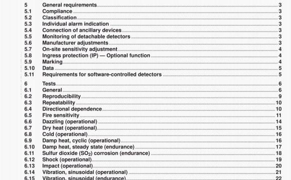
ISO 7240-10 pdf download – Fire detection and alarm systems —Part 10: Point-type flame detectors.
6.1.5.4 Source stabIlity
After determining a suitable aperture size and before any determination of response points, the irradiance on the optical axis of the source shall be measured using the radiometer in accordance with Clause A.5. This measurement shall be carried out with no modulation of the source arid with the aperture unobstructed. The measured value of irradiance shall be recorded and used as a reference throughout the test program to verify that the source radiance has not varied by more than 5 %.
6.1.6 Test procedure
6.1.6.1 Connect the specimen to its supply and indicating equipment and allow it to stabilize for a period of
15 mm or for a time specified by the manufacturer. During this stabilization penod, shield the specimen using the shutter in accordance with Clause A.3 from all sources of radiation which can affect the determination of the response point.
6.1.6.2 Before commencing any measurement of the response point, allow the burner to reach a stable working condition.
6.1.6.3 Vary the distance of the specimen from the source arid expose the detector to the source at each distance for 30 s using the shutter, The response point. I), is the greatest di5tance, measured between the aperture and the plane of the specimen sensing element(s), at which the detector reliably produces an alarm response within each 30 s exposure. If the detector response is known to be dependent on previous exposure to radiation, then allow sufficient time before each exposure to ensure that previous exposures do not substantially affect the measurement of the response point.
6.1.6.4 For detectors having stochastic response behaviour, each value of 1) shall be the moan value of at least six repetitions of each measurement, Continue repetitions until an additional value changes the average value of I) by less than 5 %.
6.1.7 Reduced functional tests
Where the test procedure calls for a reduced functional test, the detector shall be exposed to a source of radiation that is sufficient to cause an alarm response from the detector. The nature of the source used and the duration of the exposure shall be appropriate to the product in question.
6.1.8 ProvIsion for tests
6.1.8.1 The following shall be pronded for testing compliance with this part of ISO 7240:
a) for detachable detectors, eight heads and eight bases for non-detachable detectors, eight specimens
b) the data required in 5.10.
6.1.8.2 The specimens submitted shall be deemed representative of the manufacturers normal production with regard to their construction and calibration. This implies that the mean response point of the eight specimens found En the reproducibility test (6.2) should also represent the production mean and that the limits specified in the reproducibility test should also be applicable to the manufacturer’s production,
6.1.9 Test schedule
The detectors shall be tested according to the test schedule given in Table 2. After the reproducibility test, the
four specimens having the largest value of response point (at the highest sensitivity setting) shall be numbered 1 to 4 and the remainder shall be numbered 5 to 8.
6.5.2.2.3 Ensure that the area is free of radiation sources and draughts that can affect the response of the detectors to the test fire
6.5.2.3 Test fires
6.5.2.3.1 If the manufacturer specifies class 1, perform the procedure specified in 6,5,23.5 to 6.5.2.3.11 with the distance between the fire and the detectors of 25 m from the plane of the detector sensing elements. 6.5.2.32 lIthe manufacturer specifies class 2. perform the procedure specified in 6,5.2.3.5 to 6.5.2.3.11 with the distance between the fire and the detectors of 17 m from the plane of the detector sensing elements.
6.5.2.3.3 If the manufacturer specifies class 3. perform the procedure specified in 6.5.2.3.5 to 6.5.2.3.11 with the distance between the fire and the detectors of 12 m from the plane of the detector sensing elements,
6.5.2.3.4 If the manufacturer specifies class 4. perform the procedure specified in 6.5.2.3.5 to 6.5.2.3.11 with the distance between the fire and the detectors specified by the manufacturer froni the plane of the detector sensing elements.
6.5.2.3.5 Place the lire tray contalmng n-hep(ane in accordance with Annex B.
6.5.2.3.6 ShIeld the specimen froin the fire tray.
6.5.2.3.7 Ignite the fuel and allow it to burn for at least I mm.
6.5.2.3.8 Remove the shutter and allow the detectors to be exposed to the radidt,un tram the tire ur a perixj
0430 s. At the end of the 30 s period, shield the detectors from the fire radiation.
6.5.2.3.9 Record the status of each detector during the test.
6.5.2.3.10 II all eight specimens are in the alarm condition, then the detector shall be deemed to respond to the test fire. If one or more of the specimens has failed to respond, then the detector is deemed to have failed the test.
6.5.2.3.11 Repeat the procedure specified in 6.5.2.3.5 to 6,5.2.3.10 using the methylated spirit fire, in accordance with Annex C.
ISO 7240-10 pdf download – Fire detection and alarm systems —Part 10: Point-type flame detectors
