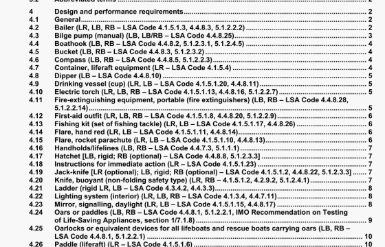
ISO 18813 pdf download – Ships and marine technology – Survival equipment for survival craft and rescue boats.
4.3.1 Performance and construction
4.3.1.1 A bilge pump shall be manually operated and designed for permanent installation in the lifeboat without Interfering with seated persons. When pumped at fifty cycles per minute. the discharge rate shall be not less than 23 I/mm for a lifeboat of less than 7,3 m in length. and not less than 32 I/mm for a lifeboat of over 7,3 m in length.
4.3.1.2 Bilge pumps shall be constructed of materials which are inherently corrosion-resistant, except that parts which are not subject to sfiding contact when the pump is in use may. alternatively, be protected from corrosion by a durable coating such as galvanizing or the equivalent. Components such as seals, elastomenc diaphragms, or other parts subject to wear, shall be designed to be user-replaceable.
4.3.1.3 Bilge pumps shall be capable of operating against a head pressure of 140 kPa when tested in accordance with 4.322.
4.3.1.4 The design of the bilge pump shall allow access for inspection, cleaning, and removal of debris.
4.3.1.5 If a bilge pump Is provided with a removable operating lever or shaft, the lever or shaft shall be provided with a set screw or other suitable means to secure it to the pump, and shall be connected to the pump body by a chain or lanyard to prevent loss.
4.3.1.6 The suction line shall be fitted with a non-return valve and a strainer. The strainer shall be removable for cleaning without the use of tools. Hoses and fittings in the suction line shall be of a type that wIN not collapse when the pump Is m service,
4.3.1.7 The pump shall be self-priming, but may in addition be provided with a means for manual priming Any removable plug or cap shall be secured to the pump by a retaining chain or cable.
4.3.1.8 II a bilge pump is of a type titled with a removable discharge hose, the hose shall be secured to the pump by a means wti.ch enables removal of the hose by hand, with a tool that Is secured to the pump by a chain or cable, or a tool which is available in the tool kit (see 4,44). The dischar9e hose shall have an inside diameter not less than that of the pump discharge openrng.
4.3.2 Testing
4.32.1 The bilge pump being tested shall be set up at a height of 1.2 m over a source of waler for operation with all the required fittings and connections, the set-up to simulate an installation In a lifeboat The bilge pump shall be operated, without manual priming, at a speed of fifty cycles per minute, and the flow of water measured. The time to first discharge of water shall not exceed 1 mm, and the discharge rate after the first discharge of water shall not be less than that required by 4.3.1.1.
4.3.2.2 A pressure gauge capable of registerIng 140 kPa. and a vanable restriction (nozzle, valve, etc.) shaM be fitted in the discharge line. The pump shall be put in operation with the discharge line open, and then the restriction shall be gradually closed until the pressure builds up to at least 140 kPa This pressure shall be maintained for at least 15s, after which the pump shall be disassembled and .nspected There shall be no destruction or deformation of parts sufficient to affect the serviceability of the pump as a result of this test
4.3.2.3 With the pump fim’ily secixed in such a position that the shaft or operating lever is fully extended and in a horizontal position, apply a dowi,ward load of 90 kg for a period of 5 mm at the free end of the shaft or operating lever and perpendicul to its axis and the axis of the shaft, There shall be no slippage of the lever around the shaft, nor any evidence of permanent set or undue stress any part of the pump. In cases where the design of the pump is such that this test may not be applicable to the complete pump, the pump shall be disassembled and the 90 kg load applied to the shaft or operating lever while the free end is held in a device or chuck so that the shalt or operating lever is In a horizontal position.
ISO 18813 pdf download – Ships and marine technology – Survival equipment for survival craft and rescue boats
