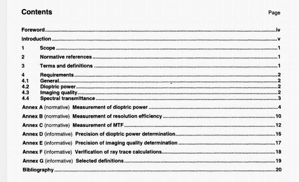
ISO 11979-2 pdf download – Ophthalmic implants —Intraocular lenses —Part 2: Optical properties and test methods.
If the measured dimensions and the refractive index of the IOL were not obtained under in situ conditions, proper corrections therefore should be made.
A.3 Determination of dloptric power from measured back focal length
&3.1 Principle
The back focal length (BR.) is the distance from the back vertex of the IOL to the focal point with parallel tight incident on-axis upon the IOL.
NOTE 1 The position of the focal pont is dependent on the spalial frequency focused at. It is not coincident with (he paraxial focal point of the lens under measurement if there is spherical aberration. The locus found is often referred to as besl focus.
In order to obtain the paraxial focal length from the measured BFL, corrections have to be made for the distance from the back vertex to the back principal plane of the IOL, and for the distance from the paraxial focal point to the best focal point.
NOTE 2 BFL and the two conections are all vector quantities. The posive direction is that of the optical axis towards (he image.
A.3.2 Apparatus
A.3.2.1 Optical bench, such as that illustrated in Figure Al, used to determine BFL.
NOTE It is a matter of convenience whether to use a straight bench or employ a mirror as illustrated m Figure A. 1.
The target is at the focus of the collimator, so that parallel light is incident upon the lOL. The focal length of the collimator shou’d be more than ten bmes (hat of the IOL. The collimator is an achromat that is virtually free of aberrations for the wavelength band transmitted by the filter. The filter shouki transmit green light with the transmittance peak close to 546 nm.
The microscope is connected to a position-measuring device so that its position along the optical axis can be determined with an accuracy of 0,01 mm,
&3.3 Procedure
Mount the IOL on the optical bench just behind the aperture.
Focus the microscope at the back surface of the lOL arid note the position of the microscope.
Focus the microscope at the image of the target and note the position of the microscope.
NOTE I Focusing should be done at a spatial frequency dose to 0,3 of the cut-oft frequency of the 101.
The distance from the back vertex of the LOL to the focal point is the back focal length, OFL. of the IOL.
NOTE 2 The procedure given here assumes that measurement is done in air at normal ambient conditions of a laboratory. The calculations assume that the dimensions of the 101 are not appreciably different under in situ condrtions. Shoiid that not be the case. BFL should be measured with the 101 under simulated in situ conditions, with appropriate changes in the calculations.
B.2 Apparatus
B.2.1 Optical bench, e.g. as illustrated in Figure A.1, having the following features:
a) a collimator achromat which is virtually free from aberrations in combination with the light source used, having a focal length preferably at least ten times that of the IOL being measured;
b) a target known as the U.S. Air Force 1951 Resolution Target (U.S. Mu Std 150-A-1961: Photographic lenses, §5.1.1.7; see Figure B.1), diffusely illuminated by a monochromatic light source of 546 nm ± 10 nm, and being in the focal plane of the collimator;
c) an aperture stop of 3,0 mm ± 0,1 mm, placed at most 3 mm in front of the IOL being measured;
d) a surrounding medium of air;
e) a microscope objective with a numerical aperture greater than 0,3 and capable of magnifying 1 Ox to 20x; and
f) an eye-piece magnifying about lOx.
B.3 Procedure
Place the IOL on the optical bench, taking care to centre it as well as possible on the optical axis of the bench.
By moving the microscope objective, focus the image of the target to obtain the best possible overall balance between coarse and fine patterns (see Figure B.1).
Then determine the finest pattern (group, element) for which both horizontal and vertical bars are resolved, with the additional requirement that all coarser patterns are also resolved. Refer to 5.3.5.1 of ISO 6328:— regarding how to determine if a pattern is resolved. Further examine the image for aberrations other than spherical aberration.
NOTE The appearance of such other aberrations are termed in many descriptive ways for which there are no proper definitions. Some commonly used words are streaking, ghosting, haze and flare.
ISO 11979-2 pdf download – Ophthalmic implants —Intraocular lenses —Part 2: Optical properties and test methods
