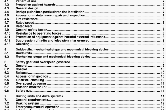
ISO 9386-1 pdf download – Power-operated lifting platforms for persons with impaired mobility – Rules forsafety, dimensions and functional operation — Part 1: Vertical lifting platforms.
The drum flanges shall project radially by no lass than two rope diameters beyond the rope pitch circle diameter. Winding drums shall be fixed to the dnving urwt shaft In accordance with 7.1.3.
7.4.3 Pulleys
Pulleys shall include additional security to retain the rope in case of wear and ageing. Tne grooves shall be smoothly finished with rounded edges. The bottom of the groove shall have the same profile as for drum grooving, but the depth of the goove shall be not less than 1.5 times the nominal diameter ol the rope. The angle of flare of the sides ci pulley grooves shall be approximately 5O.
The diameter of pulleys, measured at the bottom of the groove, shall be not less than 21 times the nominal rope diameter.
7.4.4 Angle of deflection
The maximum angle of deflection (fleet angle) in relation to the grooves shall not exceed 4.
7.4.5 Retaining of the rope
Drums, and if necessary pulleys, shall be guarded so as to ensure that the rope is retained In the grooving under all circumstances and to ensure that trapping between rope and drum or pulley cannot occur. Ropes shall also be guarded if their position is such as to create a hazard.
7.5 Additional requirements for rack and pinion drive
NOTE In order that txA advantage may be taken ci the salety potential ci this type ci dilve, particular care should be taken In the design ol the geanng from the motor to the dnving pinion and, In partla.dar, to the strength ot the output shaft
7.5.1 Driving pinion
The driving pinion shall be made from metal and shall be designed to resist wear. The safety factOr used in the design of any driving pinion shall be maintained, even after taking full account of the effects of dynamic loading, wear and latigue Iddely to arise during the designed life of the driving pinion and associated components. Undercutting of the gear teeth shall be avoided by using an adequate number of teeth. The pinion shall be fixed to the output shaft in accordance with 7.1.3.
7.5.2 DrivIng rack(s)
Rack(s) shall be made from metal having properties matching those of the pinion in wear and impact strength and shall possess an equivalent safety facter.
The rack(s) shall be securely attached to the rail(s) particularty at their ends, and means shall be provided to maintain the pinion and rack constantly in positive mesh under all conditions of load, Any pnts in the rack shall be accurately aligned to avoid faulty meshing or damage to teeth,
7.5.3 Guarding
Guards shall be titled to minimize trapping hazards between the rack and pinion and any other part (see 4.13).
7.6 AddItional requirements for chain suspension drive
NOTE Chain dnve systems thai are both fixed and guided may be regarded as rack end pinion drive systems.
7.6.1 Ct’iainwheels
All dnving chainwtieels shall be made from metal and have a minimum of 16 machinecut teeth. A minimum of 8 teeth shal be engaged, The minimum angle of engagement shall be 14O, Driving chainwheels shall b€ fixed to the drive shaft in accordance With 7.1.3.
a)maximum static hydiraulic full-oad pressure;
b)minimum safety factor of 1,7 referred to the proof stress of the materials;cminimum safety factor of 2,3 for friction losses and pressure peaks.
7.14.1.2 For the calculation of compressive stresses in jacks at their fully extended position, the following shallbe taken into account:
a)maximum pressure equal to 140 % of the full load pressure;b)minimum safety factor of 2,3.
7.14.2 Jacks
Grey cast-iron or other britle materials shall not be used in the construction of jacks and their associatedconnecting links.
The jacks shall be so mounted that they are subjected to axial loads only. They shall be provided with stops at thelimit of their stroke or with equally effective means to prevent the piston rod from travelling beyond the limits of thejack.
7.14.3 Flexible hoses
The flexible hose between the cylinder and non-return valve or the down-direction valve shall be selected with asafety factor of at least 8 relating to full pressure and bursting pressure.
The flexible hose and its couplings between the cylinder and non-return valve or the down-direction valve shallwithstand without damage a pressure of at least five times ful-load pressure. This test shall be carried out by themanufacturer of the hose assembly.
The flexible hose should be marked in an indelible manner witha)the name of the manufacturer or the trade mark,
b)the test pressure, and
cthe date of the test.
The flexible hose shall be fitted with a bending radius not less than that indicated by the hose manufacturer.7.14.4 Shut-off valve
Ashut-off valve shall be provided. lt shall be installed in the circuit which connects the cylinder(s) to the non-returnvave and the down-direction valve(s).
ISO 9386-1 pdf download – Power-operated lifting platforms for persons with impaired mobility – Rules forsafety, dimensions and functional operation — Part 1: Vertical lifting platforms
