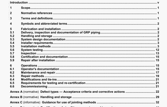
ISO 14692-4 pdf download – Petroleum and natural gas industries一 Glass-reinforced plastics (GRP) piping一 Part 4: Fabrication, installation and operation.
5.6.2.3 Testing
Water shall be admitted at a low point in the system and provision shall be made for bleeding the air at high points (e.g. by loosening of flange connections). Any compressed air in the system may give erroneous results. Removal & air pockets prevents damage to piping and personnel m the event of an unexpected failure during the pressure test.
The test pressure shall be raised over a period of 30 mm or longer to 1,5 tines the design pressure or 0.89 times the qualthed pressure, whichever is lower.
NOTE 0,89 is theh factor for occasional loads, see 7.6.2.2 .i ISO 14692-32002.
Any sudden increase in pressure shal be avoided for GRP pipework. The pressure-decay test shall be conducted for a minimum of 1 h. A further leak test, at 1.1 times the design pressure, should also be carried out for a minimum of 24 h.
The following factors influence the choice of test duration:
a) effect of joint expansion and material creep, particularty when long runs of pipe are being lasted:
b) water uptake properties of the GRP material. e.g. phenolic materials
C) effect of temperature. This is more noticeable when testing is being carried out in a hot or cold climate and if relatively lage changes in temperature may occur duflng the course of the test.
Additional checks shaM be carried out after this time has elapsed, by visual inspection of the complete piping system. Any leaking or weeping shall constitute a defect, and the test shall be terminated and a repair effected, The test procedure shall then be repeated. Over-torquing of flanges to stop leas shall not be permitted. Leaking flanges shall be remade with new gaskets and retested. If leakage still occurs, flanges shall be replaced.
The system shall be considered to have passed the hydrotest It there is no leaking or weeping of water front the piping and there is no significant pressure loss that cannot be accounted for by usual engineering considerations, e.g. thermal expansion of pipe, or other factors previously aweed with the principal.
5.6.2.4 After completion of test
Gaskets at flanged joints which have been broken for testing shall be renewed, unless otherwise agreed with
the principal.
5.7 Inspection
Visual Inspection, both internally (as far as physical access allows) and externally, shall be carned out of all joints and all surfaces. An illumination source, mirrors and other suitable aids shall be used to maximize the extent and accuracy of the visual inspection. Possible defects along with acceptance criteria and corrective actions are listed In Table 4. Further Information conceming defects erising during fabrication and mstalatlon, and corrective action, are given in Table A. 1. Further guidance on defect detection using NDEINDT methods is given in Annex E. The presence of a uniform filet of adhesive is an indicator that an adhesive ioint has been assembled correctly.
Details of repaIr methods for use dunng the fabrication and installation phase are described in 5.9.2.
6.1.3 System drawings
All relevant as—built drawings and records shall be available and maintained. It is recommended that as a minimum these include the following details:
a) pipe nominal diameters and pipe wall thicknesses:
b) key layout dimensions:
C) location of supports/restraints:
d) fire classification and location of fire-rated pe. if applicable:
e) conductivity classification, location of conductive pipe, location of earth-rounding points, earth continuity
requirements, frequency and method of inspection.
614 Inspection strategy
The principal shall provide the operator with an inspection strategy to identify system criticality and the requirements for inspection. GRP piping systems shall be inspected at regular intervals, In accordance with the inspection strategy. to ensure that the piping system is in a satisfactory state consistent with its continued operation. Further informalion about possible defects is given in Table k 1. NDE methods recommended for use in detecting defects which are most likely to occ during operation of GRP piping systems are given in Table 5 along with recommended acceptance criteria. Possil,Ie causes and recommended corrective actions are also mcluded.
6.2 MaIntenance and repair
6.2.1 Maintenance
6.2.1.1 General
GRP pipes are generally maintenance-free, but the following points shall be given attention during inspection.
6.2.1.2 Removal of scale and blockages
Care shall be taken in the use of conventional methods for removal of scale and other blockages (e.g. high- pressure water lances, mechanical and chemical cleaning methods). The manufacter’s recommendations shall be followed in all cases.
ISO 14692-4 pdf download – Petroleum and natural gas industries一 Glass-reinforced plastics (GRP) piping一 Part 4: Fabrication, installation and operation
